Erection View Member Labels
- General Overview
- Examples
- Tips and Tricks
- Related Tools
Label Positioning
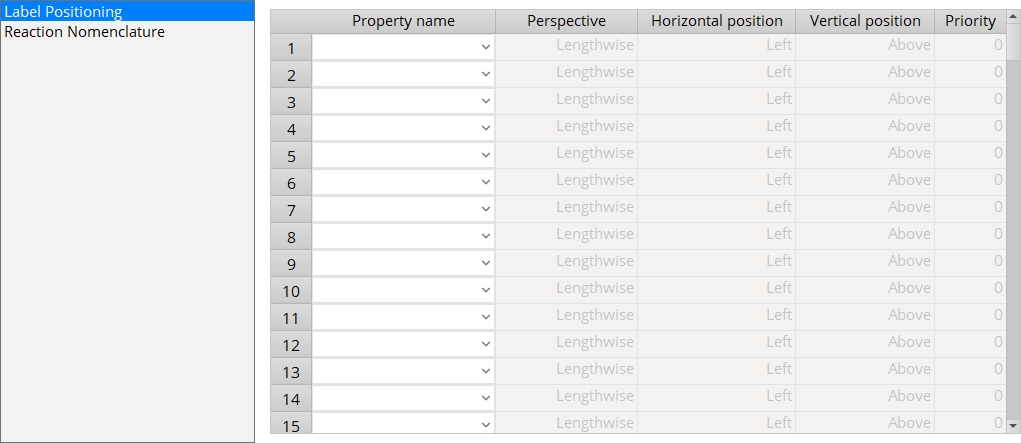
Property name: Piecemark or Section size or Camber or Left elevation or Right elevation or Shared elevation or ABM piecemark or Left vertical shear or Right vertical shear or Left horizontal shear or Right horizontal shear or Left story shear or Right story shear or Left moment or Right moment or Left panel moment or Right panel moment or Left tension or Right tension or Left compression or Right compression or Left tie force or Right tie force or Any custom property that is Added. In a Modeling erection view, values entered for these properties can be displayed as labels using controls that are found on the Display Options window. These same values can be displayed on erection drawings which are generated using Detail Erection Views and can be modified using Erection View Cleanup.
Tip: To clear a row, right-click it and select Erase row.
Note: Any member custom property appears as a selectable option in the combo box only when the box for
is checked for that particular member schema entry. Add to Erection View Member Labels
| Piecemarks | Section sizes | Camber | Elevations |
|
|
|
|
Perspective: Lengthwise or Cross section.
|
|
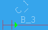
The member C_1 in this example is shown in a cross section perspective. The member B_3 is shown lengthwise. |
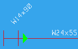
Lengthwise is a perspective that shows both ends of the member. Lengthwise perspectives of members in stick form show the longitudinal axis (length) of an individual member.
Cross section is a perspective that shows, at most, only one end of the member. A cross section is a flat plane cut at right angles to the member axis and therefore shows the depth and width (or flange width) of the member.
Horizontal position: Left or Left center or Center or Right center or Right.
|
|
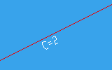
The camber annotation C=2 is shown at the center of the beam's member line in this example. |
|
|
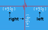
B_3 is shown on the left end of the member line. C_1 is shown to the right of the cross section. |
Left places the item on the left end of the member line when the member's Perspective is Lengthwise.
Vertical position: Above or Below.
|
|
The vertical position of the camber annotation, C=2, is below the member line in this example. |
|
|
Both of the piecemarks, C_1 and B_3, are shown above the member line in this example. |
Above places the item above the member line when the member's Perspective is Lengthwise. For a Perspective of Cross section, it places the item above the center of the member.
Below places the item below the member line when the member's Perspective is Lengthwise. For a Perspective of Cross section, it places the item below the center of the member.
Priority: 1 or 2 or 3 or 4, etc. This controls a label's proximity to the member line when multiple labels are mapped to the same location. The label under the Property name whose Priority is numerically the smallest is placed closest to the member line.
|
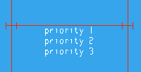
The priorities set for these labels determine the location of the labels with respect to their proximity to the member line. |
In the example above, all three labels have the same Horizontal position (Center) and the same Vertical position (Below). The label priority 1 has its Priority set to 1 and is placed closest to the member line. The label priority 2 has a priority of 2 and is placed under priority 1. The label priority 3 has a priority of 3.
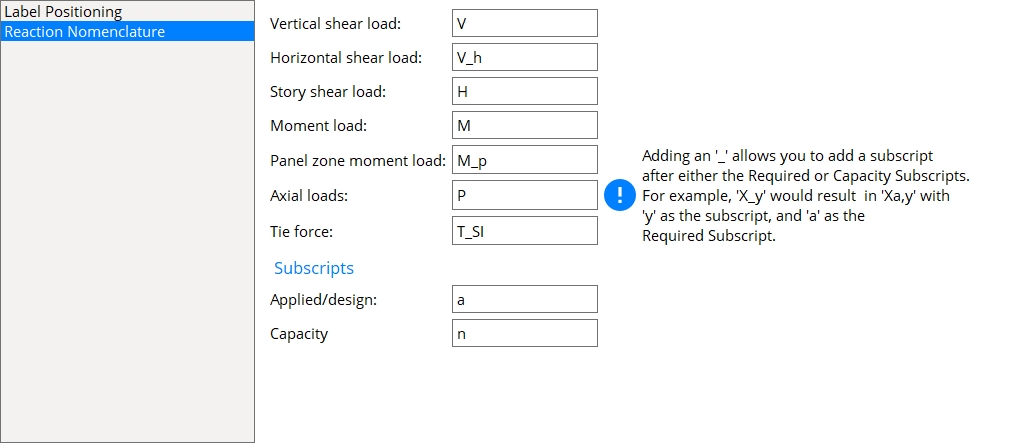
Reaction Nomenclature
The default symbols and subscripts for each type of load found on a Structural Steel member edit window's  Loads
Loads
-
End reaction annotations in the model when Display Options > End Reactions
is checked with the appropriate Display filters set. -
End reaction annotations on a 2D erection view when Detail Erection View Defaults > Annotations > End reactions is set to Both or User or Auto.
Symbols
Symbols represent a particular end reaction found on a member edit window's Loads
When changing a symbol, any string character (letters, numbers, symbols, and spaces) can be used (5 characters max.). When adding an underscore
Example 1: Typing Xy in one of the symbol fields results in an annotation of Xya.
X = symbol
y = secondary subscript added to the symbol
a = primary subscript for required loads
Example 2: Typing X_y in one of the symbol fields results in an annotation of Xa,y.
X = symbol
a = primary subscript for required loads
y = secondary subscript added to the symbol
Example 3: Typing X_y_z in one of the symbol fields results in an annotation of Xa,y_z.
X = symbol
a = primary subscript for required loads
y_z = secondary subscript added to the symbol
Vertical shear load: applies to the following structural steel member types for the corresponding Loads
Beam - Shear load
Joist - Load
Horizontal shear load: applies to the following structural steel member type for the corresponding Loads
Column - Horizontal shear
Story shear load: applies to the following structural steel member type for the corresponding Loads
Beam - Story shear
Moment load: applies to the following structural steel member types for the corresponding Loads
Beam - Moment load
Column - Moment
Panel zone moment load: applies to the following structural steel member type for the corresponding Loads
Beam - Panel zone moment load
Axial loads: applies to the following structural steel member types for the corresponding Loads
Beam - Tension load (abbreviation is shown as -Pa) and Compression load (abbreviation is shown as +Pa)
Column - Load (two abbreviations are shown: +Pa and -Pa)
Vertical brace - Tension load (abbreviation is shown as -Pa) and Compression load (abbreviation is shown as +Pa)
Horizontal brace - Tension load (abbreviation is shown as -Pa) and Compression load (abbreviation is shown as +Pa)
Tie force: applies to the following structural steel member types for the corresponding Loads
Subscripts
Subscripts are used to indicate whether the symbol's annotation is reporting the required loads or the capacity loads.
When changing a subscript, any string character (letters, numbers, symbols, and spaces) can be used (3 characters max.).
Applied/design: This subscript indicates that the symbol is displaying the required load used by connection design. The required load is the automatically generated or user-entered value that populates any one of the fields found on the member edit window's Loads
Capacity: This subscript indicates that the symbol is displaying the capacity load generated by connection design. The capacity load is the allowable strength of a particular limit state.


|
|
OK (or the Enter key) closes this screen and applies the settings.
Cancel (or the Esc key) closes this screen without saving any changes.
Reset undoes all changes made to this screen since you first opened it. The screen remains open.
Example 1
|
||
|
How to reproduce the example shown above:
At Project-creation time: The Flavor that was selected to create the custom properties used in the example was a modular flavor. You could use a legacy flavor to get the same results that are shown above, but the intermediary steps in these instructions assume that you selected a modular flavor.
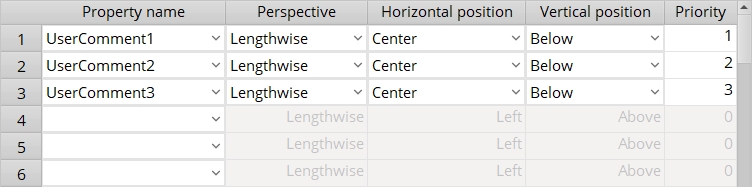
Creating the properties: UserComment1 and UserComment2 and UserComment3 are each the Name of a schema entry that was created by pressing the Add button on the Edit Schema window. The Type of each of these schema entries is String. A Prompt of User comment 1 or User comment 2 or User comment 3 was entered for each schema entry.
was checked for each schema entry. Note : Checking the box for is not required for creating a member label since a user can simply type the Property name instead of selecting it as described in the next paragraph. On this window: UserComment1 and UserComment2 and UserComment3 were each selected as a Property name and each were specified to be output at the same location (center of member line, below the member line). A different Priority was assigned to each of the property names. This setup is illustrated in the screen shot shown above.
After closing this window, the MEMBER Edit Properties window was opened (in Modeling), and the entries priority 1 and priority 2 and priority 3 were made to the fields User Comment 1 and User Comment 2 and User Comment 3 under the
leaf. Note: The MEMBER Edit Properties window is opened by pressing the Properties button that is found on a member edit window. As you can see in the screen capture shown above, the member was a beam in a plan view. In Display Options, the box was checked for
. When OK was pressed to close that window, the property labels were displayed in the model as shown in the screen capture above. For 2D drawings: The option
instructs auto detailing to place custom property member labels onto an erection view drawing.
Example 2
|
||
|
|
Notes concerning the example 2:
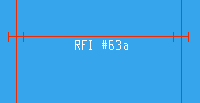
Setup is exactly the same as for example 1: The difference is that a custom property value -- in this case, RFI #63a -- was entered to User Comment 1 under the
leaf in the MEMBER Edit Properties window. The custom property entry fields for the other two properties -- User Comment 2 and User Comment 3 -- were left blank. Consequently, RFI #63a is the only custom property label that is shown on the member in this example.
Example 3
Note that there is a Number of studs field on the Beam Edit window. You may prefer to use that option instead of creating a custom property.
The video makes use of the Bruce Vaughan parametric StudCount_Cust_Prop.py. That parametric lets you enter shear stud counts to members without your having to open a member edit window. For that parametric to be able to Run, you need to have added a member custom property whose Entry name is ShearStuds and whose Type is String.
- To clear a row, right-click it and select Erase row.
- To get a custom property to be selectable using the Property name combo box, you need to -- for the desired custom property -- check the box for
- Changes made to a member label's location on this window are immediately applied to erection views in Modeling. In the Drawing Editor, however, changes are not applied to existing erection view drawings until you re-detail the erection view. To apply changes to member labels that have been moved in the Drawing Editor (e.g., by a user dragging them),
-
Settings applied to the Erection View Member Labels screen are for your current Fabricator. A different set of settings will apply when you Change Fabricator.
- Add to Erection View Member Labels (to add a Property name to this window)
- Custom properties (Display Options in Modeling, for displaying property labels)
- Show custom properties on member (to get custom properties on erection view drawings)
- Relocate piecemarks and other member labels to default locations (resets label locations)

